A wide variety of oilfield applications make use of formation water compositions but formation water samples are often contaminated with drilling mud making their compositions unreliable.
Fortunately, it is possible to correct for the effects of contamination if an aqueous tracer is added to the mud because this allows the degree of contamination of formation water samples to be quantified (e.g. McCartney et al., 2015).
The use of tracers for this purpose requires careful planning and implementation so in this post I’ll take you through the four steps that will help you select and use aqueous tracers (a) to provide accurate and sensitive quantification of contamination of your formation water samples and (b) to minimise uncertainties in the corrected formation water compositions.
1 Consider the factors important to tracer selection
To quantify mud contamination, an artificial tracer is added to the mud aqueous phase (MAP). Tracers may be added to the MAP of both water- and oil-based muds. Dyes, alcohols, tritiated water, deuterium oxide, and ionic salts (e.g. Br–, I–, NO3–, SCN–, Li+) have all been used as aqueous tracers in drilling muds. Sometimes, naturally-occurring constituents in the mud (e.g. K+ in a KCl-polymer mud, Cs+ in Cs-formate mud) can also act as tracers of mud contamination.
Each of these tracers has a unique set of characteristics that needs to be matched with the conditions expected in your well. The following factors should be considered when selecting a drilling mud tracer:
Tracer stability. For the tracer to provide an accurate measure of mud contamination of a formation water sample it should be stable (i.e. thermally, chemically and biologically) in the environment in which it is used, and non-volatile. This means it should not significantly be ‘lost’ in the well or surface facilities during drilling and similarly if it should invade the formation.
Equally, the tracer should not significantly react with any materials with which it comes into contact (e.g. the drilling fluid, reservoir hydrocarbons, formation minerals, formation water, drilling/testing equipment, etc.).
I use the term ‘significant’ because it does not matter if some degradation or reaction occurs, as long as the effect on tracer concentrations is sufficiently small that it does not affect the accuracy and sensitivity of quantification of mud contamination.
Formation water concentration. For the tracer to provide a sensitive measure of the MAP in a formation water sample, it is preferable that the naturally-occurring concentration of tracer in the formation water is low or negligible. By implication, it is necessary to understand these natural levels. If the natural concentrations are likely to be high, there may be greater uncertainty when quantifying the MAP contamination and particularly in samples with lower MAP fraction. This is because it can be challenging to sufficiently constrain high natural concentrations. Also, the MAP tracer concentration will have to be much higher too (see below). This can lead to increased uncertainty in contamination quantification where dilution is required before analysis. It may also make the material costs of the tracer prohibitively expensive.
Handling requirements. The tracer must be soluble in the MAP, and should be safe and easy to use. There may be regulatory requirements associated with tracer use, handling and disposal. These will vary with the drilling location, the tracer selected and the concentrations involved (i.e. in both concentrated form and in the dosed mud).
When using water-based muds, it is easy to separate the aqueous phase for tracer analysis by filtering the mud and analysing the filtrate. Oil-based mud emulsions can be broken using a solvent (e.g. propylene glycol normal-propyl ether, PNP) allowing the separated MAP to be analysed after filtration. Where tritium or deuterium are used with oil-based muds these tracers can also be easily analysed in water separated by Dean-Stark extraction.
Cost. The cost of using the tracer will include material, operational and analytical costs. The choice of tracer might be limited by budgetary requirements.
Tracer analysis. Preferably it should be possible to rapidly analyse the mud for its tracer content at the rig site. This will enable the tracer concentrations to be monitored, and hence controlled, during drilling which will improve the accuracy and sensitivity of contamination quantification.
For the selected analytical method, the limit of detection, accuracy and precision of tracer analysis in both drilling fluid and formation water should be appropriate for the required accuracy and sensitivity of contamination quantification. For example, it is not likely to be useful if the analytical limit of detection is equivalent to, say, 10% contamination (i.e. you will not know how contaminated your lower contamination formation water samples are). Similarly, poor analytical accuracy and precision will translate into poor accuracy and sensitivity when quantifying contamination.
2 Select your tracer to match your well conditions
Every well will be different. For example, different formation temperatures, different drilling fluids, different formation waters, different budgets, and different regulatory requirements. For this reason, the tracer needs to be selected after considering each of the factors noted above and those conditions specific to your well. A tracer that is suitable for one well might not be suitable for another and often compromises have to be made. For example:
- K+ and Li+ may be good tracers where the reservoir has low clay content (and hence low cation exchange capacity). But, both these tracers are affected by ion exchange reactions and so may be too ‘reactive’ to be used where the reservoir has high clay content.
- NO3– is prone to be affected by bacterial degradation, but where microbial activity can be prevented (e.g. using biocides) or where conditions would not support microbial activity (e.g. high formation temperatures), its use as a tracer may be an option.
- Br may be a good tracer when the formation water has low salinity because the natural concentration of Br in the formation water will be low. But, when high salinity formation water is present in the reservoir, Br may not be the best tracer to use because the natural Br concentration of the formation water is likely to be high.
- Deuterium oxide (a form of water that contains a larger than normal amount of the hydrogen isotope, deuterium, 2H) is a useful tracer for the aqueous-phase in oil-based muds because it can be quantitatively extracted in this phase via Dean-Stark extraction. It is also unreactive. Previously, it could not be analysed at the rig site (it is analysed by mass spectrometry), and so it could be difficult to control during drilling, but now specialist companies are offering on-site analysis services. It does have some limitations, however. It is used in the nuclear industry and so there may be restrictions on where it can be shipped and what it can be used for. It is also expensive, can interfere with NMR logging, and is often present at relatively high natural concentrations in formation water. However, if (a) the location allows shipment of the tracer, (b) oil-based muds are being used, (c) the formation water deuterium concentration can be sufficiently constrained, (d) costs are within the well budget, (e) on-site analysis can be performed and (f) any interference with NMR logging can be accommodated, this might be the preferred tracer for the well.
- Tritiated water (a radioactive form of water where the usual hydrogen atoms are replaced with tritium, 3H, the nucleus of which contains one proton and two neutrons), may also be an option in this latter case. It also requires specialist techniques to be measured in oil-based mud at the rig site, but it is unreactive, usually very low in formation water, and relatively cheap to use. There are regulatory requirements for dosing drilling fluids with tritium so experienced and licensed personnel need to be used (although once dosed, the mud is safe to handle and dispose of).
Evidently, careful consideration of many factors is required to select the optimal tracer in your case. Your choice may be aided by acquiring analogue information from others using the tracer under similar conditions, by geochemical modelling (e.g. to predict tracer behaviour) and by undertaking laboratory testing.
3 Carefully plan and implement field use of the tracer
Having selected your tracer, it is important to apply field methods and procedures that ultimately ensure that good accuracy and sensitivity are obtained when quantifying contamination. This will limit the uncertainty on the estimated formation water compositions if mud contamination corrections are required and is particularly important if your subsequent formation water samples are more contaminated (say, >15% MAP) when uncertainties on corrected compositions can be large.
To ensure accuracy and sensitivity, the tracer concentration should be dosed and controlled within specified limits. A reasonable target tracer concentration would be sufficiently high that the uncertainty on the level of formation water contamination would be approximately ±1% MAP at 10% MAP. This requires consideration of the limit of detection (LOD) and precision of analysis, as well as the natural concentration in the formation water. For example, this would require a target concentration of approximately 400 mg/L given an LOD and formation water concentration of <0.1 mg/L, and an analytical precision of ±9% (3 x Relative Standard Deviation, RSD).
A reasonable target variability of the tracer would be less than ±8-10% of the dosing concentration or less than ±3 times the precision of the analyses (i.e. 3 x RSD), whichever is higher.
You might obtain your formation water samples from core (e.g. via ultracentrifugation) or from the well after drilling (e.g. during formation testing). To help maintain control of the tracer concentrations during the drilling it is best to add the tracer just before the zone of interest is drilled/cored (e.g. coring target or formation water sampling target). For oil-based mud this will probably be at the start of the well section in which the targets are located because the mud is likely to be pre-prepared with tracer. For water-based mud, tracer should be added to the circulating mud approximately 40-80m before the shallowest target depth to allow time to control the dosed concentration before reaching the target.
It also helps to drill the section using low mud invasion techniques. This reduces the degree of contamination in core samples and reduces the ‘pump-out’ time to obtain low contamination formation water samples during formation testing. If low contamination samples can be obtained, this minimises uncertainties in the corrected formation water compositions. Mud invasion can be reduced through applying low overbalance, low pump rate, and high ROP, and using a low invasion bit design and oil-based mud (or, less preferably, water-based mud with good filter cake formation).
After initial dosing, it is important that the tracer concentration be maintained inside the target variability until after the coring target has been passed (core samples only) or formation water sampling has been completed.
Maintenance of the tracer concentration can be achieved by using pre-tracered mud from the reserve mud pits when mud losses have occurred and by direct addition of tracer to the active mud pit if tracer dilution occurs (e.g. due to formation water inflow or rig cleaning water inflow).
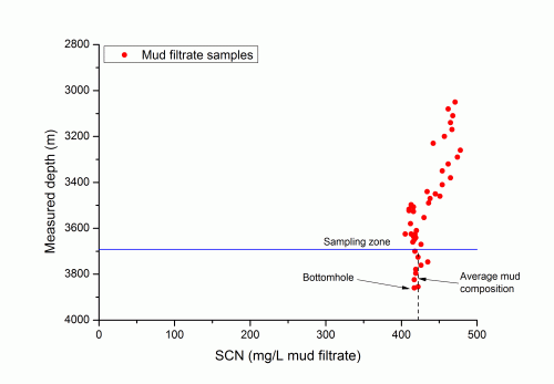
To aid control of tracer concentrations in the mud, mud samples should be regularly collected from the circulating mud system and analysed at the rig site for the tracer. Typically, samples may be collected every 10-20m drilled depth but collection may be more frequent on initial dosing, if rapid changes in tracer concentration are occurring or if you require more detailed characterisation of tracer variation with depth. Tracer concentrations in the reserve pits should also be monitored to ensure they are within target ranges before use of this mud.
To allow mud contamination corrections to be undertaken at a later date, it is also important that mud samples be collected for later laboratory analysis (i.e. to be analysed along with the formation water samples). These samples will be analysed for the tracer, to provide a quality check on the rig analyses, and a range of other constituents for which the formation water samples will be analysed (e.g. Na, K, Ca, Cl, SO4, etc.).
Where core samples are to be obtained, the mud samples should be collected before, during and just after each cored section (i.e. every 1-3m or 30 minute intervals, whichever comes sooner). Where formation water sampling is to be undertaken, sufficient mud samples should be collected to characterise general trends in tracer concentrations between the target sampling zones and completion of sampling (e.g. every ~10-20m). All tracer and mud samples need to be time-lag depth-corrected.
Decisions on which of these mud samples should be analysed can be made after completion of drilling and formation water sampling. The objective will be to ensure that the composition of MAP that may be contaminating the formation water samples is well constrained.
4 Review the performance of the tracer
On completion of drilling, it is important to review the tracer results obtained from both the mud samples and the formation water samples to establish whether the tracer shows any evidence of loss or gain (e.g. due to reaction, instability, etc.) under the conditions of use. This information will be important for (a) selection of tracers for future wells and (b) understanding uncertainties associated with estimated formation water compositions after mud contamination corrections have been applied. An example of this type of review is included in McCartney et al. (2015).
Sometimes, water samples may be opportunistically collected and so a tracer will not have been added to the drilling mud beforehand. In these cases, naturally-occurring constituents in the drilling fluid might be used as ‘natural’ tracers of contamination. For example, K+ might be such a tracer where a water-based KCl polymer mud has been used. A review of the natural tracer results will help demonstrate whether or not they are likely to provide accurate and sensitive quantification of contamination of your formation water samples.
To conclude….
If you will be collecting water samples from your well, you should apply an aqueous tracer to your drilling fluid. Then, follow these four steps:
- Consider the factors important to tracer selection.
- Select your tracer to match your well conditions.
- Carefully plan and implement field use of the tracer.
- Review the performance of the tracer.
These steps will help you to obtain accurate and sensitive quantification of mud contamination of your formation water samples. Along with the use of low mud invasion techniques to minimise sample contamination, they will also help you reduce uncertainties in the corrected formation water compositions.
Where a tracer has not been added to the drilling mud, naturally-occurring constituents in the drilling fluid might be used as ‘natural’ tracers of mud contamination of your formation water samples.
Aqueous tracers are also added to drilling fluids to allow mud contamination corrections to be made to water saturation measurements on core samples. Although not the focus of this post, much of the above is also relevant to the use of tracers for this application.
Acknowledgements. Thank you to Jon Spencer (Tracerco) and John Downs (Formate Brines Ltd) for their useful comments on a previous version of this post (their comments have been included above).
If you have any comments or questions about this topic, please e-mail ross@oilfieldwaterservices.co.uk and I will include these and any additional information in future updates to this post.
Useful references
McCartney R. A., Aarrestad H. D., Lien S. K., Ramstad K., Sæther Ø., and Johnsen R. I. (2015) Reactive transport modelling of mud filtrate invasion during drilling and application to mud contamination corrections on formation water analyses prepared for the 26th International Oilfield Chemistry Symposium, 22-25 March, Geilo, Norway.
Armstrong, F. E., and Lovelace, K. (1961) A study of core invasion by water-base mud filtrate using tracer techniques: Drill and Prod Prac, API, p. 104-113.
Hodder, M. H., Samir, M., Holm, G., and Segret, G. (2004) Obtaining formation water chemistry using a mud tracer and formation tester in a North Sea subsea field development, paper SPE 88637 in Proceedings SPE Asia Pacific Oil and gas Conference and Exhibition, Perth, Australia, 18-20 October.
Hutchins, R. D., and Dovan, H. T. (1991) Aqueous tracers for oilfield applications, paper SPE 21049 in Proceedings SPE International Symposium on Oilfield Chemistry, Anaheim, California, U.S.A., 20-22 February.
Millar, R. H. G., and Buckles, R. S. (1975) Tritiated water as a drilling mud tracer in Beaufort exploration wells: Journal of Canadian Petroleum Technology, v. 14, p. 42-47.
Zemel, B. (1995) Tracers in the oil field, Elsevier – Developments in Petroleum Science, 514 p.

